Addressing Dynamic Transient AI Workloads: Introducing the RTQ1954 80V Hot Swap Controller
Mohammad Etemadrezaei | AN092 October 2025

In the complex and ever power-increasing modern datacenters, the operational efficiency and scalability requirements lead to modular systems such as servers, add-in-cards, and aux boards that must be plugged in or removed while the system remains powered. At the forefront of it is a hot swap controller (HSC) that facilitates the hot (un)plugging while protecting downstream systems during dynamic and wide transient loads. This application note will introduce the Richtek RTQ1954 hot swap controller and its multi-level overcurrent protection (OCP) design, highlighting how it ensures reliable protection for dynamic AI workloads while enabling thermal optimization for high-power systems.
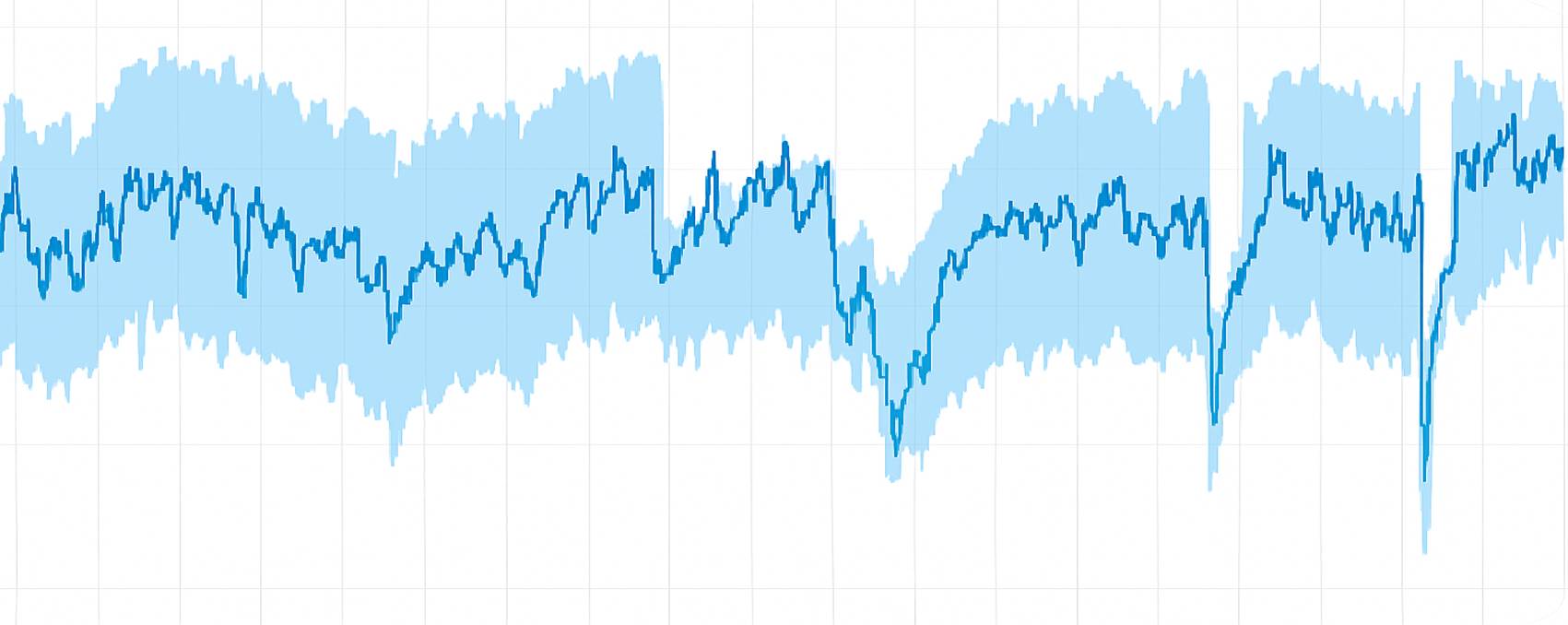
Figure 1. Example of AI Workload with Wide and Dynamic Transients
1. Applications and Challenges of Hot Swap Controllers
1.1 Applications
Hot swap controllers are typically used in modular systems such as data center servers, most commonly at the power entry port (see Figure 2). These controllers have three main functions:
1. Facilitate plugging and unplugging into a live busbar,
2. Protect the system during failures,
3. Provide critical telemetry for power and security management purposes.
To do so, a hot swap controller controls one or several external series pass devices, such as a MOSFET (connected in parallel depending on the power requirements).
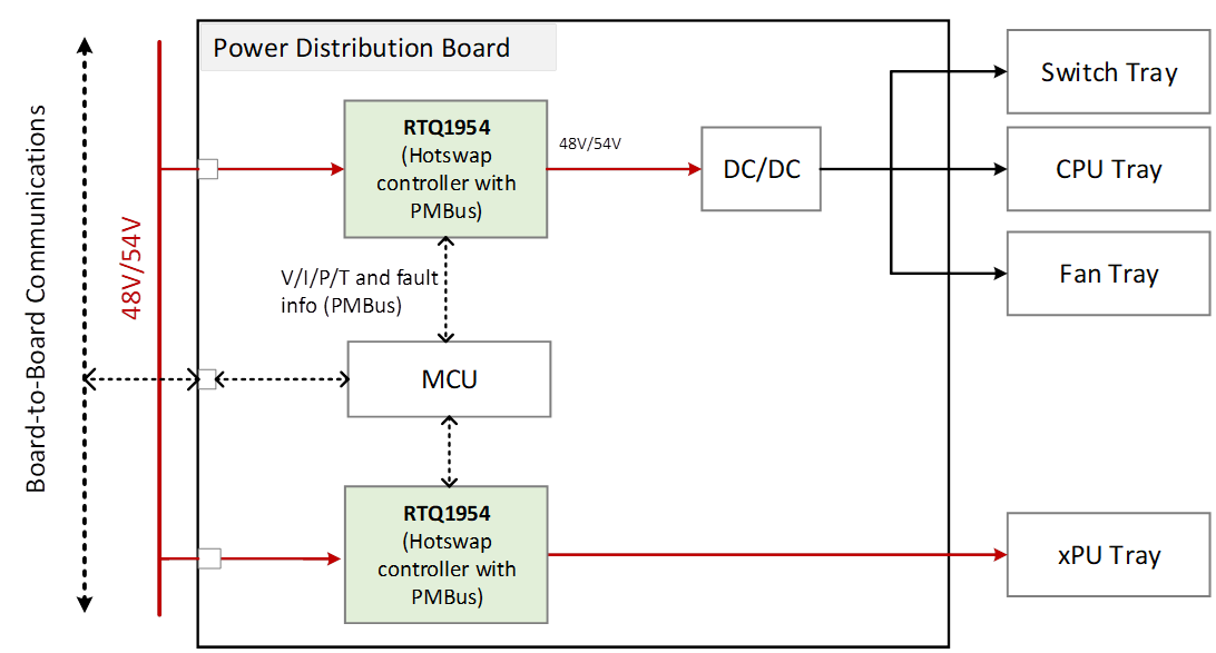
Figure 2. A Typical Application for a Hot Swap Controller in a Power Distribution Board
1.2 Challenges
A scenario where hot swap controllers protect the system is during an overcurrent event, either at start-up or during steady-state operation. Other than an output hard short with low resistance to GND (where the controller will shut down the MOSFET within few a μs due to excessive overcurrent), most hot swap controllers actively limit the current (and/or power) for a certain duration (fault timeout period) before turning off the MOSFET. This type of protection mechanism works well when the load profile is well known and does not include wide transient spikes.
Modern xPU load profiles serving AI applications have wide and dynamic transients with varying durations that are not confined within a tight specification as in a CPU load profile. Protecting such a load profile with a single current/power limit can result in an unexpected fault and thus requires:
1. Setting the current limit threshold above the maximum expected load profile, and/or
2. Increasing the fault timeout period to allow transient load surges to pass.
The issue with increasing the current limit threshold is that it leaves a large gap for overcurrent events, such as soft short, to go undetected, see Figure 3. The issue with increasing the fault timeout period is the elevated stress on the MOSFET during the fault that can violate its SOA limits.
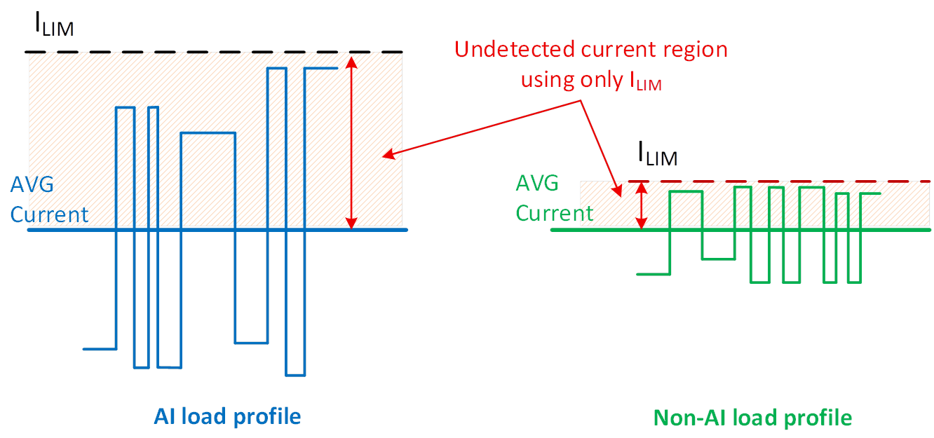
Figure 3. With Single-Level Overcurrent Protection (ILIM), the Hot Swap Controller Faces Challenges in Properly Protecting Systems with AI Load Profiles
1.3 Solution
The Richtek RTQ1954 hot swap controller solves the AI dynamic load profile protection challenges using multi-level overcurrent protection (OCP). The multi-level OCP is highly flexible and can be tailored to protect a variety of load profiles. This application note discusses the benefits of multi-level OCP and how it helps protect an 8.5kW system with a load profile shown in Figure 4.
2. Multi-Level OCP
The RTQ1954 provides four levels of fast and accurate protection against a variety of overcurrent loads, as shown in Figure 4.
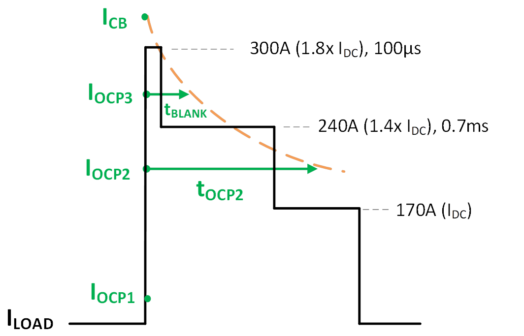
Figure 4. Multi-Level OCP Setting for a Dynamic Load Profile with Multiple Steps of Various Durations
| Overcurrent Protection |
ΔVSNS Threshold (Voltage Across Sense Resistor) |
Fault Timer |
| OCP1 (Start-Up Only) |
2mV |
Immediate |
| OCP2 |
10mV to 55mV (PMBus), 26mV, 37mV to 49mV, and 50mV (hardware) |
Set by CTIMER |
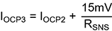
| OCP3 |
VOCP2 + 15mV |
0.5ms |
| CB |
50mV, 100mV, 200mV |
Immediate |
Start-Up Protection, OCP1: Protects against unexpected and excessive inrush currents.
Normal Operation, OCP2: Intended to be set above the steady-state load to protect against soft shorts or unexpected overloads lasting longer than programmable timeout set by a capacitor at the TIMER pin.
Normal Operation, OCP3: Allows even higher than expected short overload pulses to pass through and still protects the system if the overload condition exceeds tBLANK (typically 0.5ms).
Circuit Breaker, CB: With sub-μs response to extreme overcurrent events, circuit breaker is the ultimate protection against severe fault conditions.
Throughout this note, the following system parameters are used:
| Parameter |
Value |
| Input Voltage |
50V |
| Average DC Current |
170A |
| Average DC Power |
8.5kW at 50V |
| OCP1 |
8A/Immediate |
| OCP2 |
200A/1.19ms timer |
| OCP3 |
260A/0.5ms timer |
| CB |
400A/Immediate |
| Number of MOSFETs |
6 x PSMN2R3-100SSE |
2.1 Start-Up Protection, OCP1
During start-up, a capacitor from the GATE pin to GND is used to implement soft start, thereby limiting the VOUT slew rate and reducing the inrush current to the output capacitor. If the output capacitor is damaged or shorted to GND, the inrush current can be significant, leading to excessive power dissipation in the external MOSFET (VDS close to maximum as VOUT is 0V). In high-power applications with multiple MOSFETs in parallel, in a worst-case scenario only one MOSFET conducts the whole inrush current due to the mismatch of the MOSFETs' VGS thresholds.
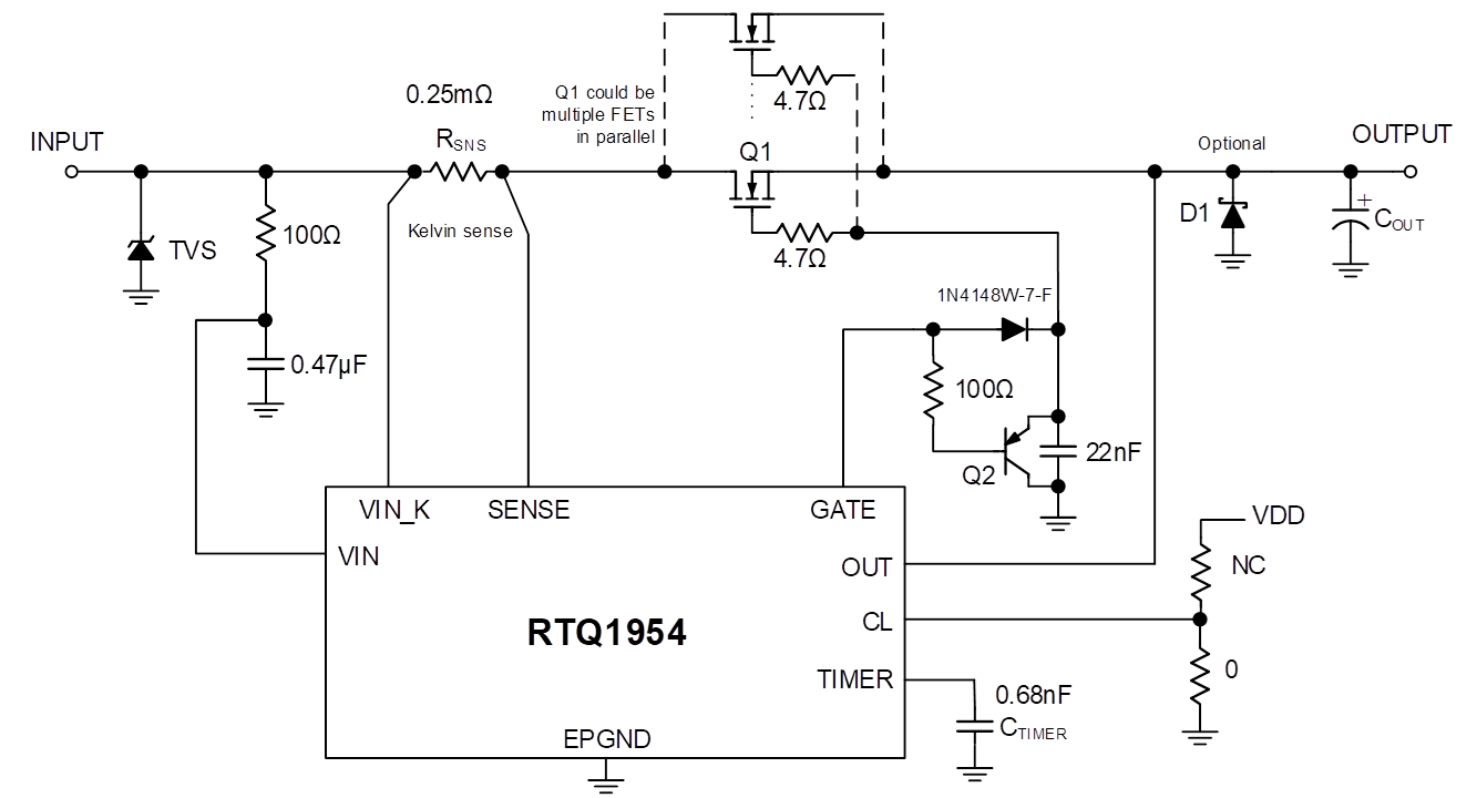
Figure 5. Simplified Application Circuit
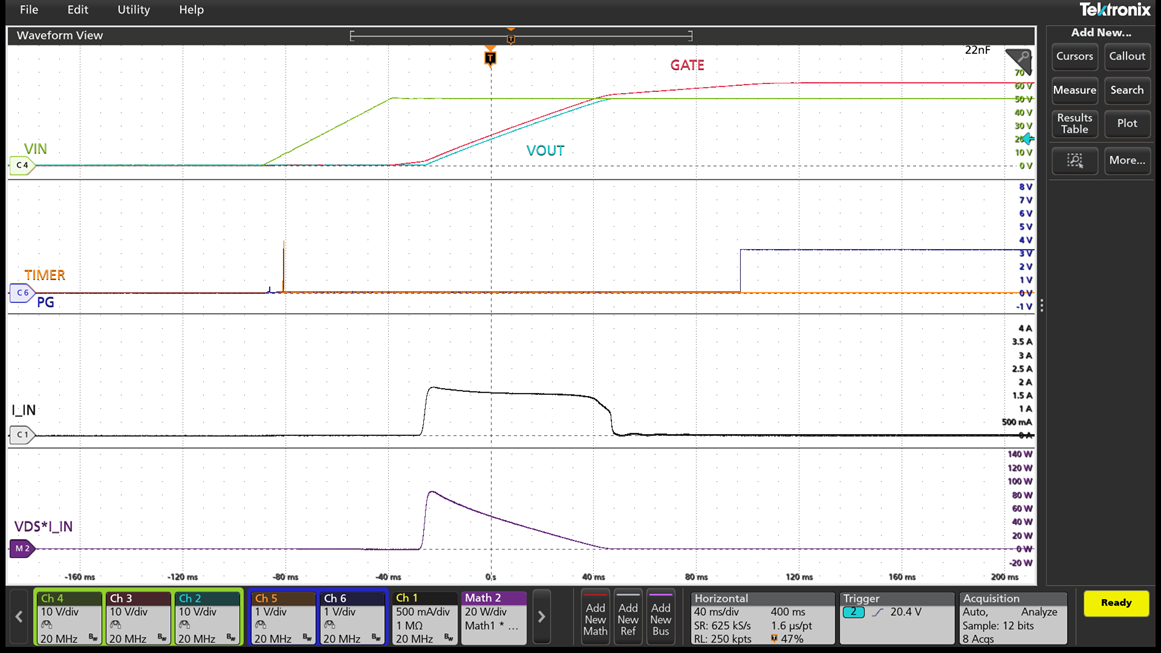
Figure 6. Start-Up Sequence (VIN=50V, CGATE=22nF, COUT=2400μF, tSTART=72ms, IINRUSH=1.7A)
To protect against start-into-short, the RTQ1954 implements a fast overcurrent protection, OCP1, that immediately turns off the external MOSFET if the current reaches IOCP1 threshold (voltage across the RSNS exceeds the 2mV threshold). OCP1 protection response is immediate and does not regulate current and/or power in the external MOSFET for a timeout duration. The benefit is the reduced stress in the MOSFET particularly in start-up where there is large voltage across the MOSFET.
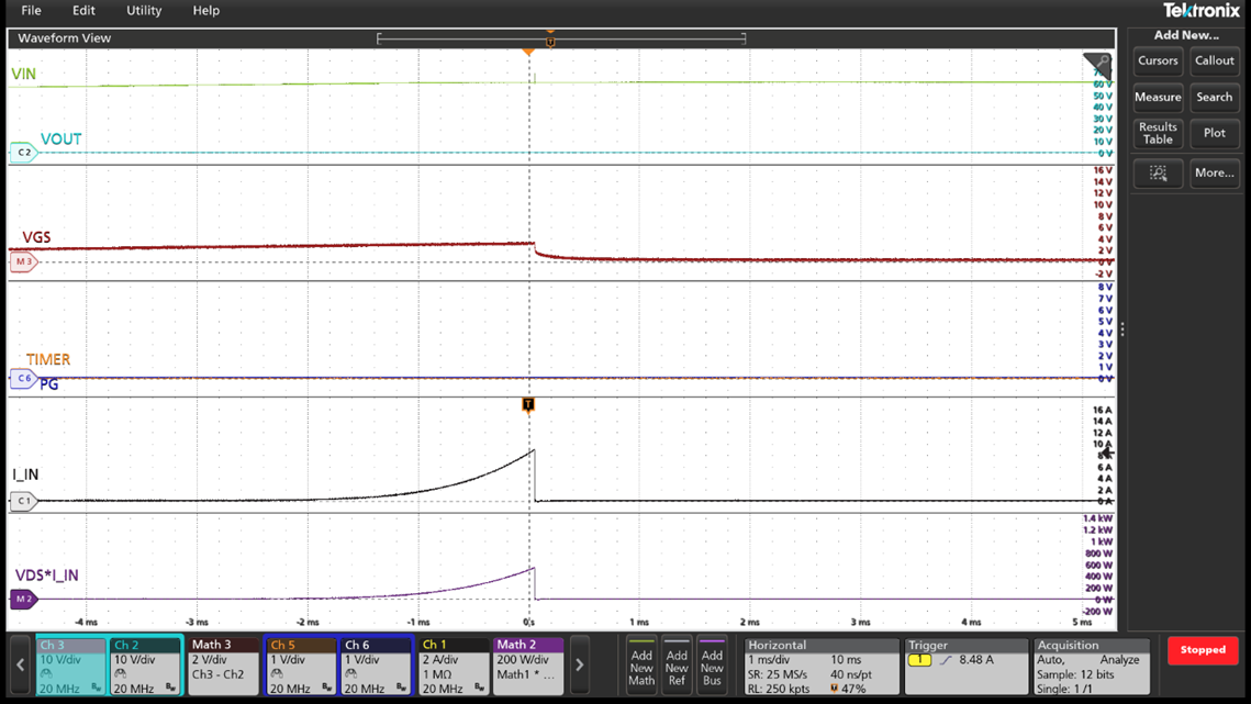
Figure 7. Start into Short, as the Current Reaches IOCP1 (10A), the RTQ1954 Shuts Down Immediately
2.2 Steady State Protection, OCP2
After power-up, the HSC needs to monitor the current for abnormal overcurrent events and protect the system. The RTQ1954 actively measures the load current by monitoring the voltage across RSNS. When the load current reaches IOCP2 threshold (IOCP2=VOCP2/RSNS), the fault timer starts by charging CTIMER with 2.5μA. If the current drops below the IOCP2 threshold before the fault timer reaches the fault timeout period (CTIMER voltage reaches 3.9V), the RTQ1954 resumes normal operation and CTIMER is discharged using 20μA. Otherwise, if the OCP2 lasts longer than the fault timeout period, the RTQ1954 turns off the external MOSFET and discharges CTIMER using 20μA. The tOCP2 fault timer is set by
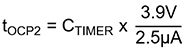
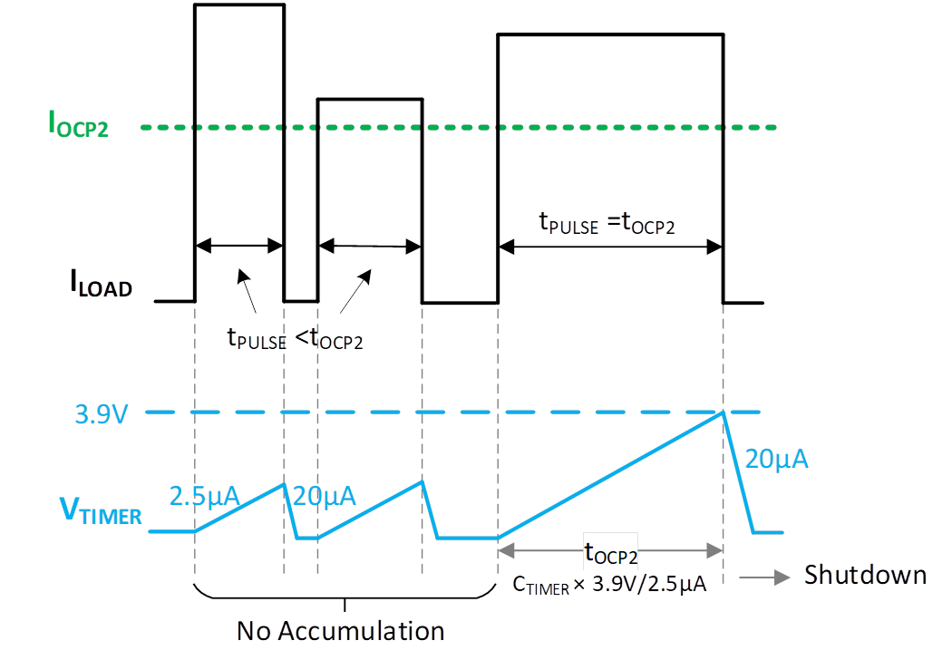
Figure 8. OCP2 Protection Mechanism.
Having multi-level OCP, the first level of protection does not need to be set above the maximum expected load profile, exposing the system to undetected soft shorts. It is recommended to set the IOCP2 just above the IDC (accounting for IOCP2 tolerance and VIN fluctuations) as a first level of protection against persistent overcurrent events, such as soft short, or longer than expected transient overloads.
The VOCP2 threshold can be set through PMBus (10mV to 55mV with 1mV increments) or through hardware using the CL and VAUX pins. This provides great flexibility to fine tune the IOCP2 without modifying the RSNS.
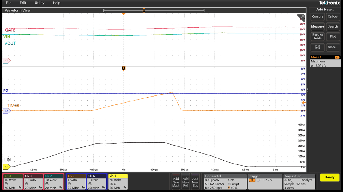
Figure 9. TIMER Starts Ramping when Current Reaches IOCP2=200A. The Current Drops below IOCP2 before the TIMER Expires (VTIMER<3.9V). (VIN=50V, RSNS=0.25mΩ, VOCP2=50mV, CTIMER=0.68nF, tOCP2=1.19ms)
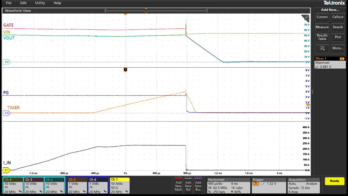
Figure 10. TIMER Starts Ramping when Current Reaches IOCP2=200A. The Current Does Not Drop below IOCP2 before the TIMER Expires (VTIMER<3.9V) and Faults. (VIN=50V, RSNS=0.25mΩ, VOCP2=50mV, CTIMER=0.68nF, tOCP2=1.19ms)
2.3 Steady State Protection, OCP3
Wide dynamic load profiles can have current bursts to more than 2xIDC that can last several hundreds of microseconds. The HSC should allow such short surges while protecting against an actual fault. The RTQ1954 provides another level of protection, OCP3 above OCP2, designed to pass through short high-current pulses that last less than 0.5ms. The IOCP3 threshold is set with an offset above IOCP2 as
If the current pulse exceeds the IOCP3 threshold and lasts longer than the 0.5ms blanking time, the RTQ1954 shuts down the external MOSFET. Otherwise, if the pulse is shorter than the blanking time, the RTQ1954 resumes normal operation, and the blanking timer immediately resets ensuring unpredictable and repetitive short pulses pass through without tripping.
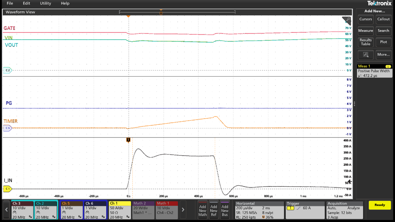
Figure 11. The Load Current Pulse above IOCP3=260A Lasts Less than the Blanking Time (tBLANK=0.5ms), the Pulse will Go Through without Tripping a Fault.
2.4 Circuit Breaker Protection, CB
Circuit breaker is the ultimate protection mechanism for overcurrent events, such as output short circuit, where the current can exceed the IOCP2 and IOCP3 thresholds faster than they trip a fault. The circuit breaker mechanism is activated when the voltage across RSNS exceeds the threshold set as VCB (choice of 50mV, 100mV or 200mV). In this event, the RTQ1954 immediately switches off the MOSFET. Following the current dropping below the ICB threshold, the RTQ1954 allows the MOSFET to turn back on instead of latching off (this is to ensure sudden input voltage steps are not mistaken for short-circuit faults and do not shut down the system). If the short-circuit fault still exists, either OCP2 or OCP3 triggers the fault. Following the CB event, the TIMER pin current (that sets the OCP2 timer) is increased by 10x to 25µA to quickly turn off the MOSFET and keep its power dissipation within the SOA limits.
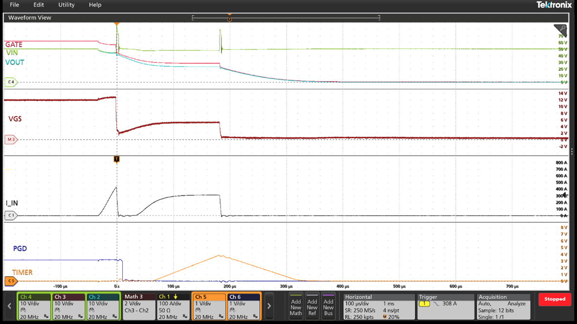
Figure 12. After the CB Operation, the RTQ1954 Allows the MOSFET to Turn Back ON (without Current Limiting) while OCP2/3 will Protect the System if the Short Still Exists. The TIMER pin Current is Increased to 25µA to Quickly Turn Off the MOSFET. Auto-Retry Disabled, VIN=50V.
3. Preventing False Faults in Repetitive Overcurrent Loads
One of the characteristics of the AI load profile is the repetitive overcurrent pulses with duty cycles reaching beyond 50 percent. The HSC at the entry point of the system, needs to distinguish between repetitive overcurrent bursts and sustained overcurrent faults to avoid triggering on false faults. RTQ1954 addresses this issue by providing a fast fault timer that resets the moment current drops below the OCP2/OCP3 thresholds, leaving the HSC ready to protect against the next overcurrent event.
The RTQ1954 OCP3 timer is digital and immediately resets the fault timer the moment current drops below the IOCP3 level. The OCP2 fault timer is analog and is set by CTIMER. When the current goes above IOCP2, CTIMER is charged using a 2.5μA current, and when the OCP2 event is ended (whether or not VTIMER reaches 3.9V at the end of the event), the CTIMER is discharged using a 20μA current. This fast discharge current (8:1 discharge/charge ratio) ensures the VTIMER is reset to zero voltage before the next OCP2 event starts. Thus, preventing the VTIMER ramping up from a pre-bias voltage and accumulating, leading to false fault tripping.
The RTQ1954 OCP2 non-accumulation condition is up to 88% load duty cycle (defined based on load pulse that is above IOCP2), allowing for a variety of wide and unpredictable overcurrent scenarios without false fault tripping.
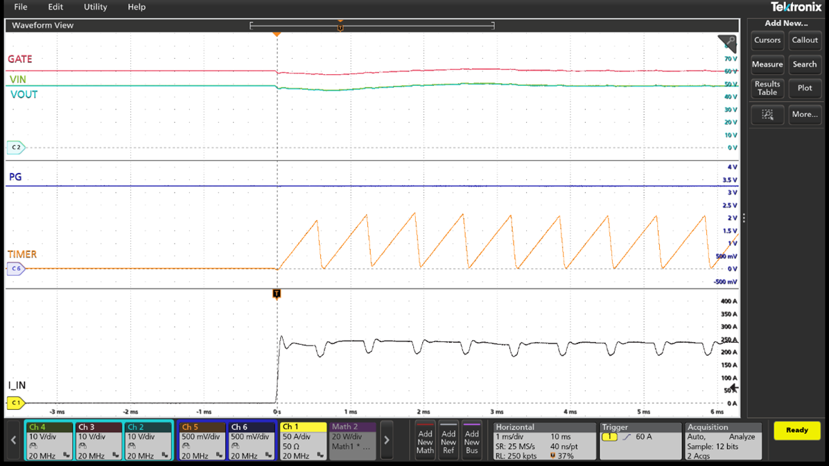
Figure 13. Repetitive Load Pulses (ILOAD>IOCP2) with Duty Cycle of 87%. The RTQ1954 VTIMER Does Not Accumulate and Avoids False Fault Tripping up to 88% Load Pulse Duty Cycle.
4. Soft Shorts Can No Longer Go Undetected
In scenarios where the output is shorted through a large enough impedance that the current does not increase significantly, the hot swap controller faces the risk of not detecting this soft short, potentially leading to thermal failure. This issue is more severe when there is only one level of overcurrent protection (other than circuit breaker) that is set 50% or even 100% above IDC to accommodate input tolerance and prevent dynamic loads triggering false positive faults.
The RTQ1954 multi-level OCP solves this issue by covering a wide range of currents through OCP2 and OCP3. Therefore, any soft short current above OCP2 will be detected. This allows system thermal designers to design the board to withstand up to OCP2 current level, vs. designing it to withstand 2xIDC.
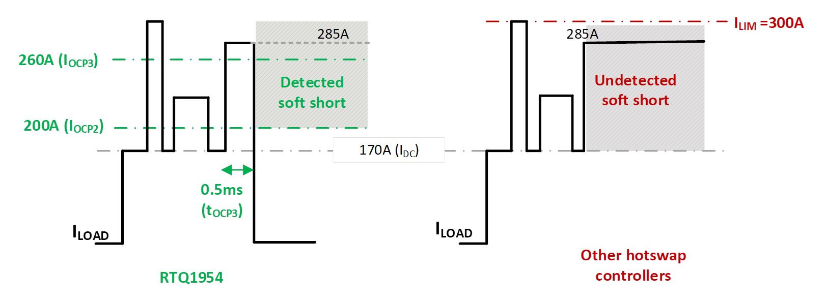
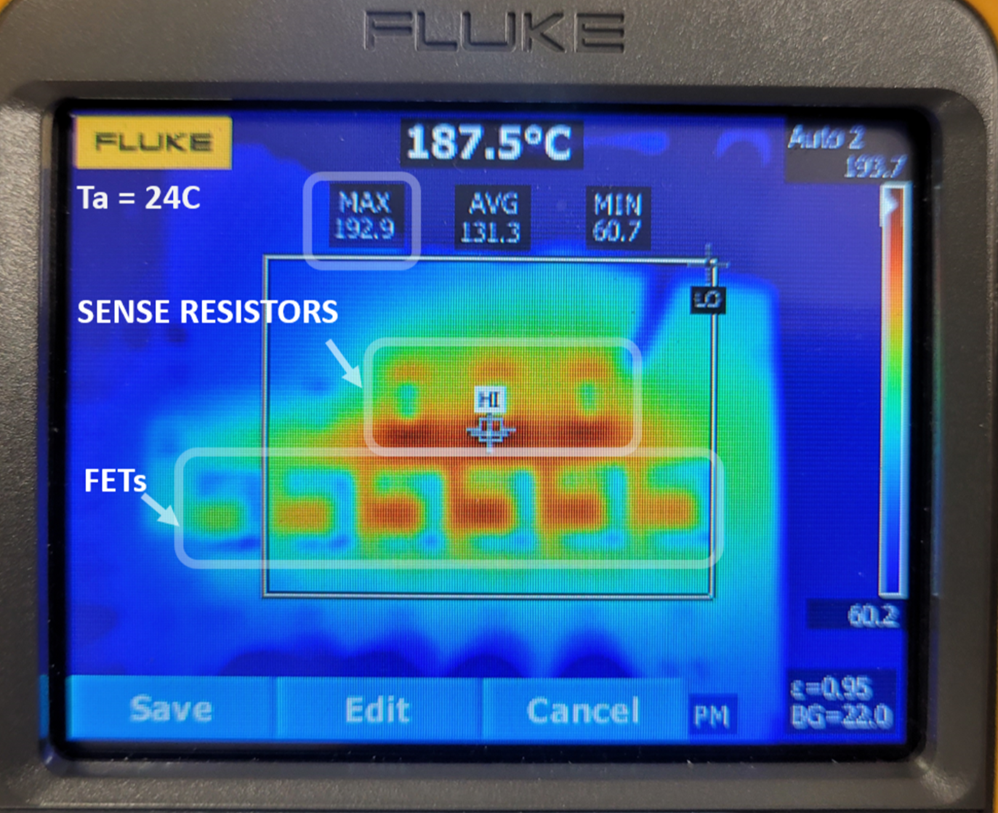
Figure 14. Example of a Soft Short and Potential Failure with Other Hot Swap Controllers Having Only One Level of Overcurrent Protection (ILIM=300A). MOSFET Case Temperature Reaching 180°C, at 285A after 4 Minutes.
5. HSC System Thermal Design Now Independent of Its Protection Design
In high-power applications, the HSC can drive multiple external MOSFETs connected in parallel. During steady state, the MOSFETs equally share their portion of the current depending on the board layout design and RDSon variations. Typical HSC thermal design will require as many MOSFETs as possible to keep the MOSFET junction temperature within its maximum operating temperature. The MOSFET used in this application is the PSMN2R3-100SSE with a low RDSon of 2.28mΩ at 25°C and a maximum junction temperature of 175°C. The number of MOSFTEs needed in parallel to keep the junction temperature TJ (similar to case temperature for this type of MOSFET) below the DC operating junction temperature TJ,DC (recommended 120°C to account for transients) is determined by:
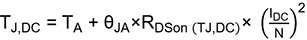
where TA is the ambient temperature.
With the MOSFET RDSon strongly dependent on its junction temperature, a few iterations of the above equation may be needed to converge on the final values of RDSon and TJ,DC. According to the MOSFET datasheet, the RDSon increases by x1.8 at 120°C vs. 25°C, which leads to a TJ,DC that is close to the target value, and no further iterations are required.

The 8.5kW (50Vx170A, DC average power) HSC system is achieved with 6 MOSFETs and 15°C/W thermal resistance between MOSFET junction to ambient (which is highly dependent on board thermal design, heatsink, and air flow). A system with higher thermal resistance than this example, would need more MOSFETs and/or lower ambient temperature to accommodate TJ,DC.
How does the HSC thermal design depend on the protection design?
The answer lies in where the first level of overcurrent protection is set, below which the system can handle sustained currents. If the first level of OCP is set to 2 x IDC (to avoid false faults for dynamic AI loads), then the thermal design must be based on 2 x IDC, leading to more MOSFETs for the same DC power.
The IOCP2 in the RTQ1954 is set just above IDC, meaning any overcurrent, including sustained soft shorts, above IOCP2 will be detected. Therefore, the thermal design can be based on IOCP2, which is close to IDC. This leads to a smaller number of MOSFETs for the same DC power.
It is worth mentioning that most HSCs have an external thermal protection mechanism that can monitor the temperature of a device such as a MOSFET. However, the thermal time constant of the MOSFETs used in this application board is in the tens-of-second range, if not more, which is much higher than the overcurrent protection timer (ms range). In addition, the HSC typically monitors the temperature of one spot. If multiple MOSFETs are used, the temperature mismatch of the MOSFETs can go undetected.
The RTQ1954 allows the HSC thermal design to be optimized according to the DC current, versus a much higher overcurrent protection level, leading to a fewer MOSFETs for the same average DC power.
6. Conclusion
Modern AI workloads have wide and dynamic transient load profiles that impose challenges to a hot swap controller used at the entry point of the system. The HSC needs to distinguish between short current bursts, repetitive overcurrent pulses, and sustained soft shorts without interrupting the load profile and more importantly without shutting down the system. The RTQ1954 hot swap controller solves these challenges with a multi-level OCP that does not limit the current, thus does not affect the load profile, yet can be tailored to protect a variety of dynamic AI workloads without triggering false faults. With increasing power levels of the modern xPU systems, the RTQ1954 system thermal design can be optimized to address average DC power, while protecting the system from various overcurrent conditions above the DC current, resulting in an optimized system.
To stay informed with more information about our products, please subscribe to our newsletter.